Inquiry
Form loading...

What Is Chemical Equipment and How Does It Work?

Chemical Equipment is the physical infrastructure that turns raw materials into controlled, useful products. It includes reactors, pumps, heat exchangers, distillation columns, filters, storage tanks, and automated control systems. Each item performs a defined task, but none works alone. A stainless-steel reactor may combine heat, pressure, agitation, and precise dosing. A heat exchanger then removes excess heat, while sensors monitor temperature, flow, and pressure every second.

The scale is substantial. The International Energy Agency’s report, The Future of Petrochemicals, identifies chemicals as the largest industrial energy consumer and links petrochemical feedstocks to about 12% of global oil demand. Its analysis also projects continued growth in chemical production and resource consumption. These figures explain why equipment efficiency, heat recovery, and process integration matter beyond one factory. Even a small pump can influence energy use, product consistency, and operational risk.

Safety remains central. The Center for Chemical Process Safety promotes layers of protection, including relief systems, alarms, shutdown logic, and operator procedures. IEC 61511 also provides a recognized framework for safety instrumented systems in process industries. Yet a neat definition can mislead. Chemical Equipment is not merely metal hardware; it is part of a living process system shaped by chemistry, maintenance, human judgment, and changing conditions. A blocked filter, worn seal, or drifting sensor can alter the entire operation. This article examines how major equipment works, where it fits within a process, and why reliable design requires more than impressive specifications. Some choices still depend on site data. That deserves careful review.
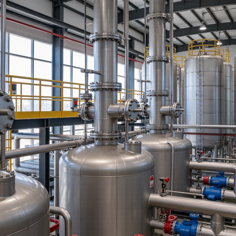
What Is Chemical Equipment and How Does It Work?

Chemical Equipment Defined: Process Roles, Energy Duties, and Core Categories

What Is Chemical Equipment and How Does It Work?

Chemical Equipment Defined: Process Roles, Energy Duties, and Core Categories

Chemical equipment includes the vessels, pipes, heat exchangers, pumps, separators, and control devices used to transform materials safely. Each item has a process role. A reactor encourages a controlled reaction, while a separator divides liquids, gases, or solids. Storage tanks provide residence time and protect material quality.

Energy duties are equally important. Heat exchangers transfer thermal energy between streams without direct mixing. Boilers add heat, and condensers remove it. Pumps increase liquid pressure, while compressors raise gas pressure. These duties affect operating costs, product consistency, and equipment life. In plant reviews, a neat process diagram can still hide poor insulation, unstable flow, or difficult maintenance access. Small design errors matter.

Tips: Check temperature, pressure, flow, and material compatibility before selecting equipment. Confirm relief protection and drainage paths during the design review. Leave enough space for inspection and cleaning. It sounds obvious. It is often missed. Operators should also compare real readings with design values, because gradual fouling can reduce heat transfer long before failure appears. Equipment categories overlap in practice. A jacketed vessel may store, mix, and heat a material. That flexibility is useful, but it can complicate control and cleaning. A reliable design documents these compromises clearly and verifies them through testing, inspection, and operating procedures.
From Feed to Product: How Pumps, Reactors, Separators, and Valves Work Together

Chemical equipment forms a controlled path from raw feed to usable product. A pump moves liquid feed from storage into the process line at a measured flow rate. Its pressure must overcome pipe friction, elevation, and equipment resistance. Flow is not just movement. It is timing. A reactor then provides space, heat, mixing, or pressure for chemical change. Inside, temperature sensors and agitators help maintain stable conditions. A few degrees can alter conversion, selectivity, or safety. In real plants, operators watch trends rather than one reading. That practical habit catches drift early.

After reaction, separators divide the mixture into useful phases or fractions. A vessel may remove gas, settle solids, or separate liquids by density. The chosen method depends on particle size, viscosity, temperature, and residence time. Valves coordinate every stage. They start, stop, throttle, or redirect flow when conditions change. Control valves respond to instruments, while isolation valves support maintenance.

Pressure matters. A pump running against a closed valve can overheat quickly. I have seen process descriptions focus on major vessels and ignore small drain lines. That is a mistake. Minor lines can affect sampling, shutdown, and contamination control.

Tips: Trace the feed with a simple line diagram. Mark each pump, reactor, separator, and valve. Check what happens during power loss, blocked discharge, or rising temperature. Confirm materials suit the fluid and operating range. Keep alarm limits understandable. They are not decoration. Review operating data with maintenance teams, because drawings can age faster than equipment. Also, question assumptions. A balanced process on paper may behave differently after fouling, wear, or seasonal temperature changes.

Heat and Mass Transfer in Practice: 20–80 Tray Stages and 70–90% Recovery Targets

What Is Chemical Equipment and How Does It Work?

Chemical equipment controls heat, flow, pressure, and composition during industrial processing. A distillation column separates liquids through repeated vaporization and condensation. Trays create contact between rising vapor and descending liquid. Each tray approximates one equilibrium stage, but real performance is lower. It is not magic.

A practical column may require 20–80 theoretical stages, depending on volatility, feed quality, pressure, and product purity. Engineers convert theoretical stages into actual trays using tray efficiency. A 60-stage design might need 80 physical trays when efficiency reaches only 75%.

Reflux improves separation but increases steam, cooling-water, and pumping demand. The U.S. Department of Energy’s Industrial Decarbonization Roadmap identifies process heating as roughly half of industrial manufacturing energy use. That makes thermal efficiency a direct operating concern.

Recovery targets commonly range from 70–90%, but they should not become automatic promises. A 90% target may increase energy use, solvent losses, or equipment size. A 70% target may be more practical when feed composition changes sharply. The International Energy Agency reports that industry consumes about 37% of global final energy, reinforcing the value of disciplined heat integration.

In field assessments, I would check tray flooding, weeping, fouling, and condenser approach temperature before accepting a simulation. Small leaks matter. Reality disagrees. Data from the U.S. DOE and IEA support measurement, but plant-specific testing remains essential.

Pressure-Vessel Engineering: ASME Section VIII Design for 1–300 bar Service

Chemical equipment includes reactors, heat exchangers, separators, and pressure vessels. In 1–300 bar service, pressure-vessel engineering demands disciplined code interpretation. ASME Section VIII defines requirements for vessel design, fabrication, inspection, and testing. Its rules protect against rupture, leakage, buckling, and excessive deformation.

A design begins with pressure, temperature, fluid properties, corrosion allowance, and cyclic duty. At the lower end, 1 bar service may not automatically fall within Section VIII’s scope. The engineer must verify the applicable jurisdiction and design pressure. Division 1 uses established formulas for common vessels. Division 2 applies more rigorous analysis and tighter quality controls. Wall thickness is only one part. No shortcut works here.

Material strength changes with temperature. Weld efficiency can reduce allowable thickness performance. External vacuum can collapse a vessel suddenly. ASME hydrostatic testing is often based on about 1.3 times MAWP, subject to code conditions and stress limits. The final calculation must match drawings, weld records, and inspection results. A spreadsheet alone is not evidence of safety. Field reviews often reveal mismatched nozzles, outdated relief settings, or missing corrosion data. These details are easy to underestimate.

The IEA’s Oil 2024 report projects petrochemicals will drive more than one-third of oil-demand growth through 2030. That expansion increases demand for reliable pressure equipment. Reliability still depends on traceable engineering decisions. Small assumptions can create large consequences.

Control and Safety Systems: Managing Temperature, Pressure, Flow, and Hazard Layers

What Is Chemical Equipment and How Does It Work?

Control and Safety Systems: Managing Temperature, Pressure, Flow, and Hazard Layers

Chemical equipment includes reactors, tanks, pumps, heat exchangers, and separation units. Their performance depends on controlled operating conditions. Temperature sensors watch the reaction vessel continuously. Flow meters confirm that materials move at the intended rate. Pressure transmitters detect changes before equipment reaches a dangerous limit.

A control system compares real-time measurements with approved operating targets. It can adjust valves, cooling water, heating elements, or pump speed. For example, rising reactor temperature may trigger extra cooling. If the temperature continues climbing, an independent shutdown system can isolate the process. Pressure relief devices provide another protective layer when control actions fail.

Good safety design uses several barriers, not one trusted instrument. Operators review alarms, trends, and field conditions from a control room. They also inspect equipment for corrosion, blocked lines, damaged wiring, and unusual vibration. A sensor can drift. An alarm can be misunderstood. No control strategy is perfect, and that weakness deserves honest attention.

Reliable facilities test shutdown functions at planned intervals. They document calibration results and investigate repeated alarms. Procedures must match the actual equipment, not an outdated drawing. Human judgment still matters during abnormal conditions, especially when readings conflict. Clear training, conservative limits, and independent protection help reduce the consequences of error.

What Is Chemical Equipment and How Does It Work? - Control and Safety Systems: Managing Temperature, Pressure, Flow, and Hazard Layers

Control or Safety Function Typical Equipment or Device Measured Variable Typical Industrial Range Normal Control Action Protective Response Typical Hazard Controlled Common Reference
Temperature control Resistance temperature detector, thermocouple, temperature transmitter, control valve Reactor, vessel, column, or heat-exchanger temperature Approximately −200 to 1,700 °C, depending on sensor type and service Adjusts heating-medium or cooling-medium flow to maintain the set point High-temperature alarm, heating shutdown, emergency cooling, or feed isolation Thermal runaway, decomposition, product degradation, and equipment damage IEC 61511; IEC 60584; ASTM E230
Pressure control Pressure transmitter, back-pressure regulator, control valve, vacuum breaker Vessel, reactor, pipeline, or distillation-column pressure From full vacuum to several hundred bar, depending on process design Modulates outlet flow, inert-gas supply, vent flow, or compressor operation High- or low-pressure trip, equipment shutdown, or isolation of the affected section Vessel rupture, implosion, loss of containment, and unstable operation ASME BPVC Section VIII; IEC 61511
Pressure relief Pressure relief valve, rupture disk, relief header, flare or recovery system Relieving pressure and relieving flow capacity Set pressure is selected below the protected equipment design limit Normally remains closed and opens automatically when the set condition is reached Discharges vapor, liquid, or two-phase flow to a safe destination Overpressure caused by blocked outlets, fire exposure, runaway reaction, or utility failure API 520; API 521; ASME BPVC Section VIII
Flow control Orifice meter, magnetic flow meter, Coriolis meter, vortex meter, control valve Liquid, gas, or steam flow rate Application-dependent; commonly specified in kg/h, m³/h, or standard m³/h Changes valve position or pump/compressor speed to match the required flow Low-flow trip, minimum-flow recycle, feed cutoff, or automatic shutdown Pump cavitation, inadequate cooling, incorrect reaction stoichiometry, and loss of process stability IEC 61511; ISO 5167
Level control Differential-pressure level transmitter, radar gauge, float switch, level control valve Liquid or solids level in a tank, separator, or reactor Commonly expressed as 0–100% of vessel operating height Adjusts inlet or outlet flow to maintain inventory and residence time High-high shutdown, low-low pump trip, or automatic feed isolation Overflow, dry running, gas carryover, loss of separation, and vessel damage IEC 61511; ISA-5.1
Basic process control system Transmitters, controllers, remote I/O, human-machine interface, final control elements Temperature, pressure, flow, level, composition, and equipment status Continuous monitoring across normal operating ranges Uses feedback control, alarms, trends, and operator commands to keep the process within normal limits Generates alarms and may initiate predefined control actions Process variability, off-specification product, utility imbalance, and operating deviations ISA-5.1; IEC 61511
Safety instrumented system Independent sensors, safety logic solver, shutdown valves, motor trips Defined high-high, low-low, high-temperature, high-pressure, or gas-detection conditions Trip points are established by hazard analysis and operating limits Usually does not regulate normal operation; it acts only when a dangerous condition is detected Moves the process to a defined safe state, such as stopping feeds and isolating energy Major release, fire, explosion, toxic exposure, and severe equipment damage IEC 61508; IEC 61511
Emergency shutdown Emergency-stop stations, isolation valves, shutdown logic, depressurization valves Fire, gas release, critical equipment failure, or manually initiated emergency signal Response time is defined by the hazard assessment and process dynamics Removes or isolates hazardous inventories and energy sources Stops pumps, compressors, heaters, and feeds; closes or opens designated valves Escalation of fire, expanding release, overpressure, and uncontrolled chemical reaction IEC 61511; ISO 13850
Fire and gas detection Combustible-gas detector, toxic-gas detector, flame detector, heat or smoke detector Gas concentration, flame radiation, smoke, or abnormal heat Combustible gas alarms are often configured as fractions of the lower flammable limit; exact values are site-specific Provides indication and alarm for operator intervention Can initiate ventilation, equipment isolation, emergency shutdown, or fire protection systems Fire, explosion, toxic exposure, and delayed emergency response IEC 60079-29-1; IEC 61511
Containment and isolation Double-block-and-bleed arrangement, check valve, containment vessel, drainage system Valve position, leakage indication, inventory, or containment pressure Designed according to fluid properties, pressure, temperature, and release scenario Keeps hazardous material within designed boundaries during normal operation and maintenance Isolates the source and routes residual material to a controlled recovery or disposal system Toxic or flammable release, cross-contamination, and uncontrolled maintenance exposure API 6D; IEC 61511
Alarm management Audible and visual alarms, alarm historian, priority matrix, operator display Deviation from normal operating or safety limits Priority commonly classified by consequence and required response time Alerts the operator to investigate and correct a developing abnormal condition May support manual intervention or be linked to an automatic protective function Alarm overload, missed critical warnings, and delayed response to process deviations ISA-18.2; IEC 62682

Note: The numerical ranges and protective actions shown are representative industrial examples. Final set points, response times, instrument selection, and safety integrity requirements must be established through process design, hazard analysis, equipment specifications, and applicable local regulations.